Sienci Mill One Upgrades
Way back in 2016 when I was running the ill fated Fabribles website, one of the many products I came across was the Sienci Mill One. At that time Sienci were just beginning and their Mill One desktop CNC was their first offering. I was pretty impressed with its simplicity and form factor and very interested in the claims that It could machine aluminium. I had long planned to build a small factor CNC and the Mill One looked like it might be able to handle the kind of work I had planned for it, namely small aluminium components. With the Mill One plans being available under an open source license it also meant that I could build one myself, but for some reason it’s taken me five years to actually make a start.
Sienci have since discontinued the Mill One in favour of their Long Mill CNC router, which has a larger form factor and many improvements. The Mill One suffered from some accuracy issues and milling aluminium, whilst possible was a slow process. Sienci do have a Mill One ‘plus’ in development, but this seems more like a cut down Long Mill rather than an upgraded Mill One as it has lost its enclosure and cool self-contained portable aesthetics which for me was tha major part of its appeal. The Mill One plus is also no longer a true desktop CNC, which by my definition is something that can literally be used on your desk. Try using the Mill One plus on your desk and you’re going to have a lot of cleaning up to do. So I decided to take a look at the original Mill One (V3) and see what improvements I could make to it to allow it to be used to machine aluminium.
Getting started
I downloaded the open source plans from the Sienci website and printed out the 3D printed parts. These already have some improvements over the original V1 parts as they now incorporate additional features, such as sturdier mountings to help prevent twisting of the X and Y assemblies within the enclosure. There is also some additional clearancing on the X and Y carriages to help extend travel.
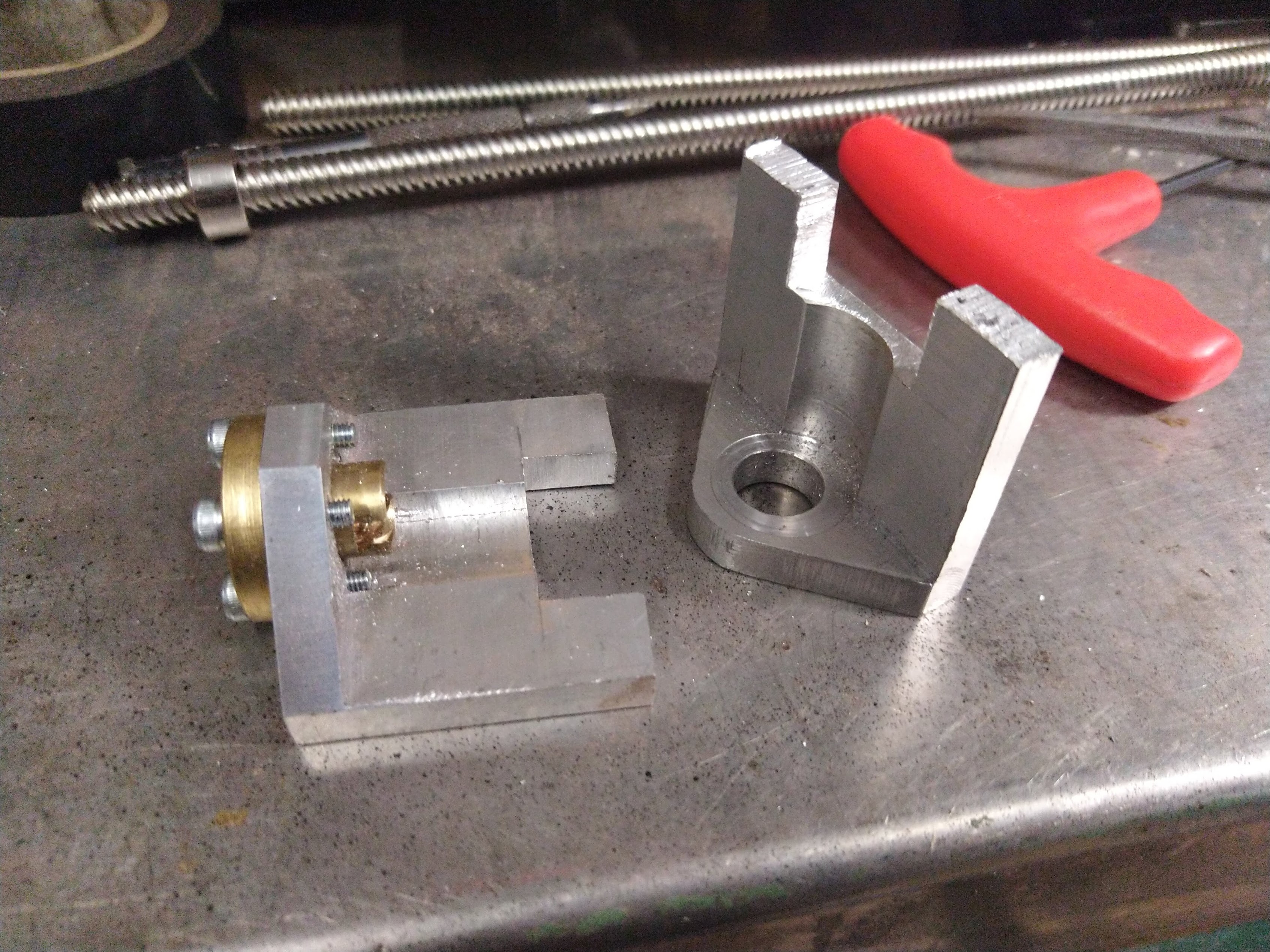
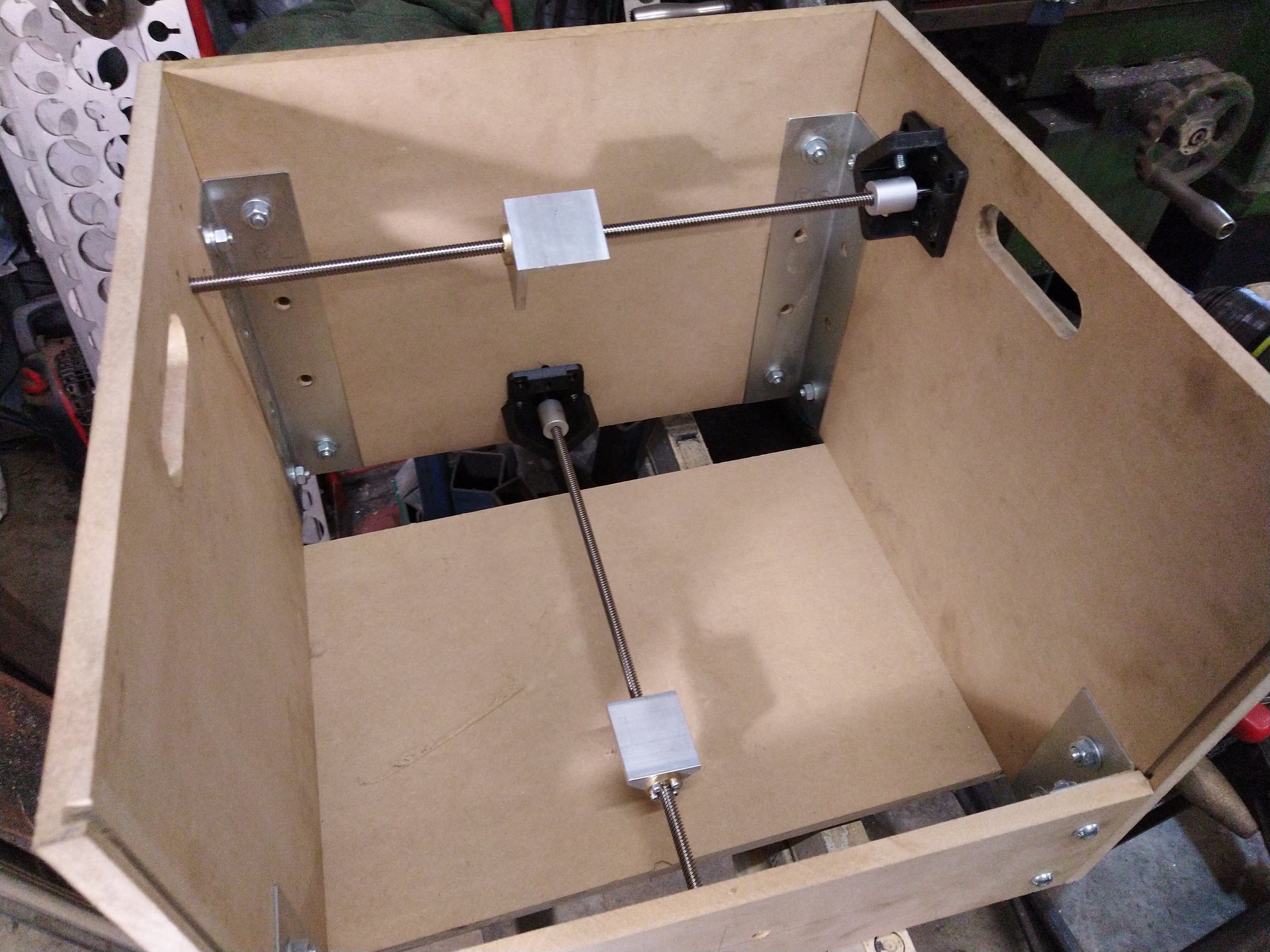
One thing that I did notice is that the leadscrew nut support blocks were very flimsy and had a tendency to crack when the nuts were bolted into position. Of course this could just be poor quality printing on my part but there’s not really a lot of material in them, which is a result of the space constraints within the aluminium angle channel where they are located, so this became the first item on the agenda. The fix for this was pretty simple, make some better ones from aluminium. Of course this may not be so accessible for everyone else as I have a machine shop at my disposal but it would be possible to replicate what I have done using simple hand tools. I took some small sections of the aluminium angle and machined them to accept the anti-backlash nuts.
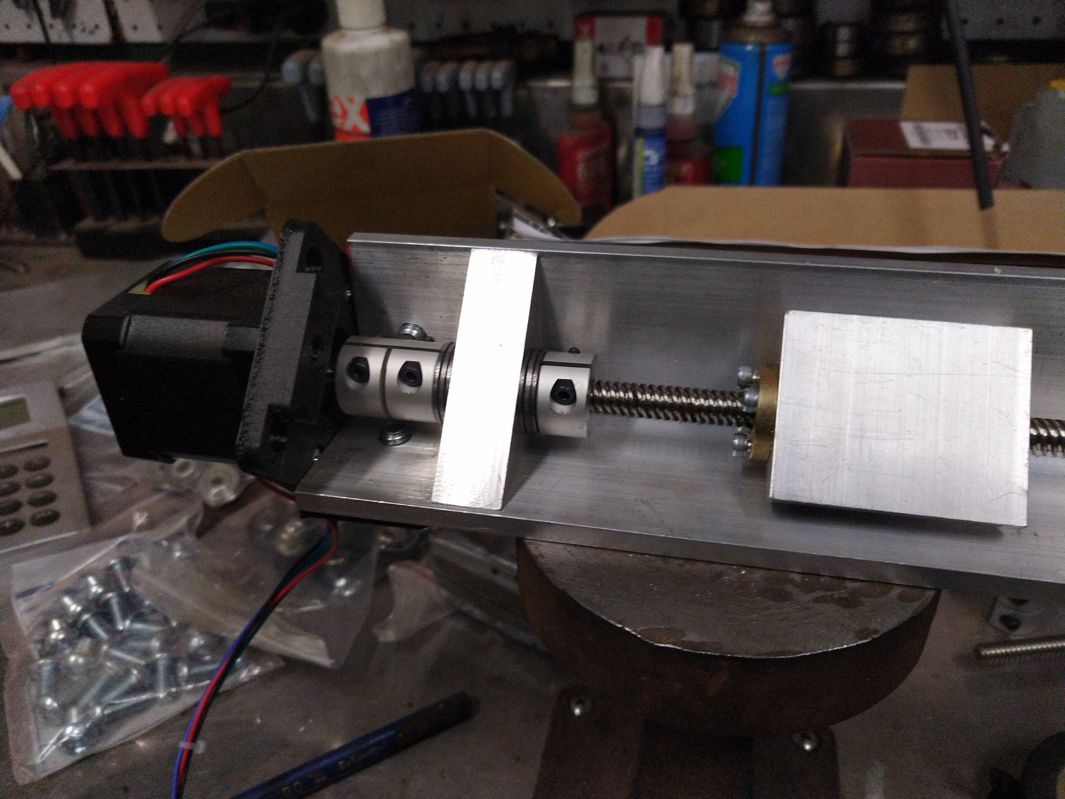
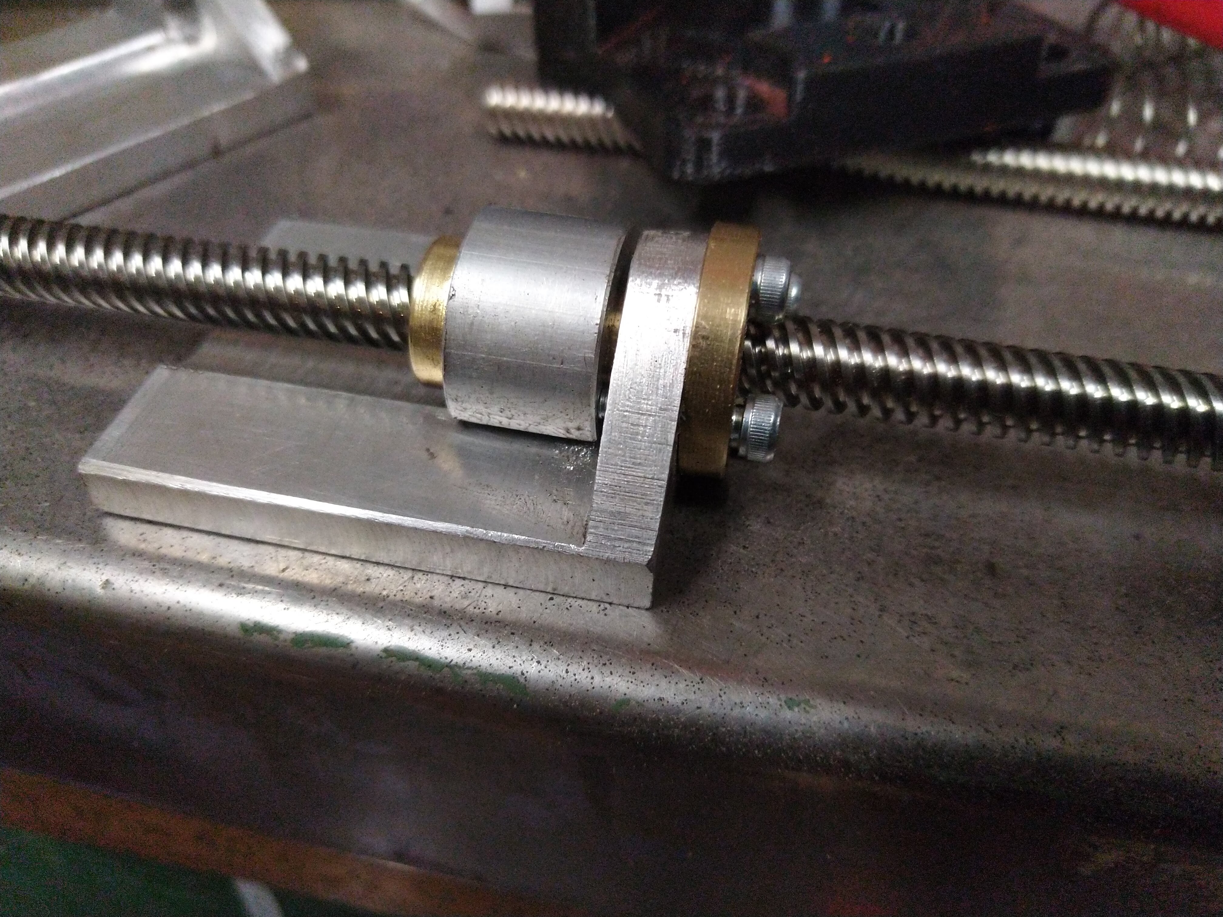
The next issue I noted was that once assembled the linear motion had a lot of movement under load. This was not all due to backlash, some was deflection caused by the spring in the anti-backlash nut but some was the stepper motor itself. There is a spring washer in the stepper motor which tended to compress depending on which direction the load was presented. Such a setup would be fine for something like a 3D printer where there is zero tool load, but for a CNC mill it is not acceptable as the tool load when cutting aluminium easily overcomes the force of both the anti-backlash nut spring and the spring washer in the stepper motor. It makes me wonder how the Mill One managed to machine aluminium at all without getting a lot of tool chatter and poor finish, this is actually something that I noted in the finish of presented aluminium parts.
To solve the backlash issue I pondered fitting ball-screws in place of the ACME lead-screws but realised that they would not fit without modifying the 3D printed mounts, which I had already printed, and so I decided to address the existing issues. The deflection of the shaft in the motor is easily fixed by adding thrust washers to the shaft to hold the shaft. In the standard Mill One design the bearings in the stepper motor take all of the tool load, which is not what they are designed for. Likewise the anti-backlash nuts use a very weak spring to take up the backlash, which means that if the tool load exceeds the spring pressure the backlash nuts do not work. My solution for this was to replace the springs with hard spacers that can be manually adjusted - much like a real mill. I did test using stiffer springs but the additional force required to turn the lead screw meant that the overall power of the machine would be reduced, which is not good as with such small stepper motors it needs all the help it can get. The net result of these two issues was over 1mm of play in line with the direction of travel of the axis. Not good for a precision machine. So these mods alone will help to tighten the accuracy down considerably and are equally applicable to all axis.
One of the ‘improvements’ that Sienci did was to decrease the length of the Z axis lead-screw by 20mm to help improve Z axis clearance as the lead screw protruded below the aluminium angle by 20mm. I did the opposite of this. I increased the length of the angle and the overall enclosure height by 20mm which nets an improvement of 20mm under the Z axis and an additional 20mm height in the workarea. Win-win.
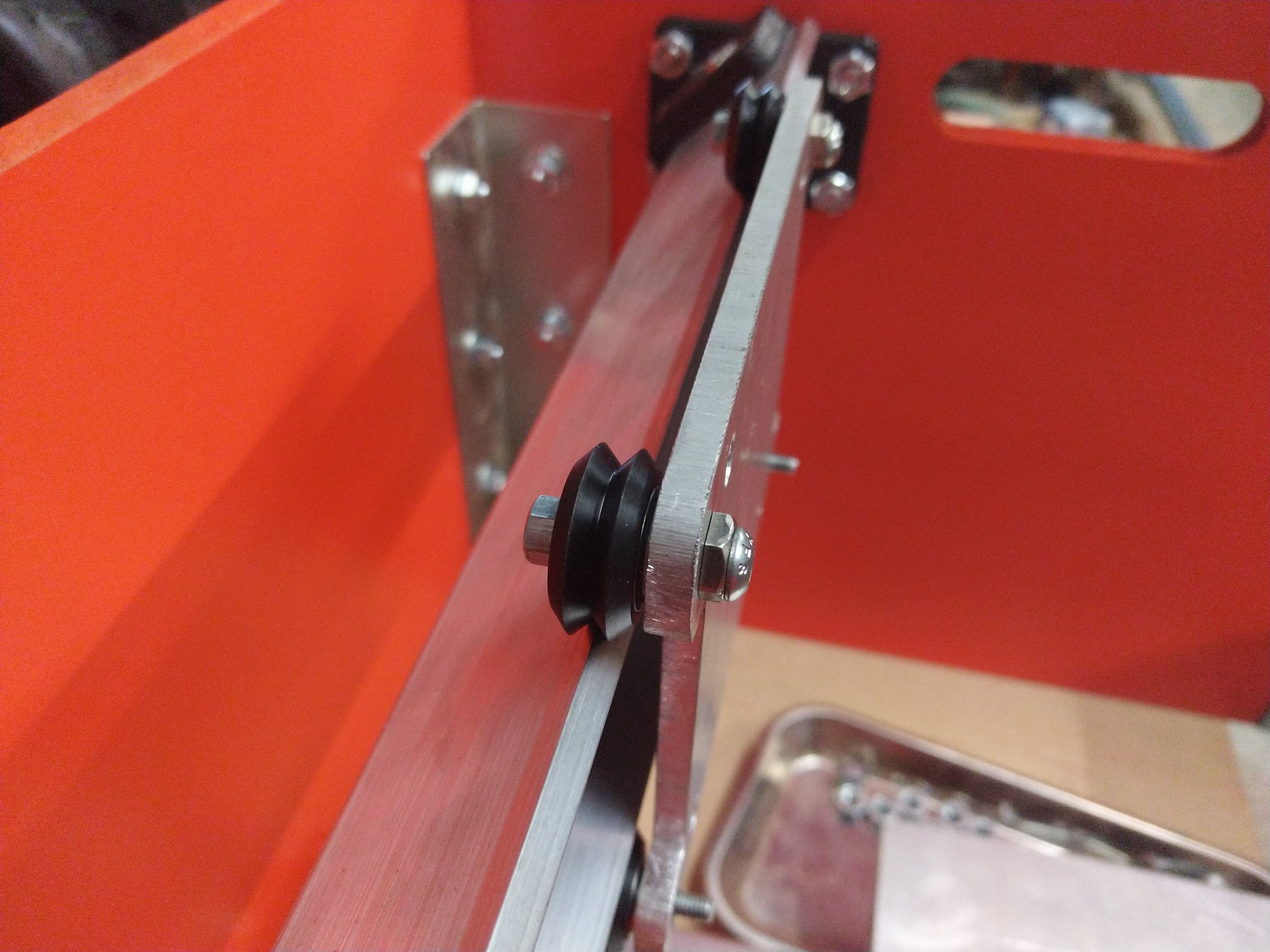
One modification that I did consider was to replace the delrin wheels with steel ones. I did have some steel Vee wheels in stock but decided against using them as they only had a single bearing in them, which meant that they had some inherent play in them, whereas the dual bearings in the Delrin wheels had minimal play due to an amount of pre-load between the two bearings. I may order some steel Vee wheels with dual bearings and compare but for the time being the Delrin ones should be fine as there is no noticeable play in the wheels themselves. Ultimately replacement of the Angle & Vee wheel setup with linear bearings would make a big improvement, especially on the Y axis but again I decided to keep to the basic design. Moving too far from the original concept simply makes it a different machine.
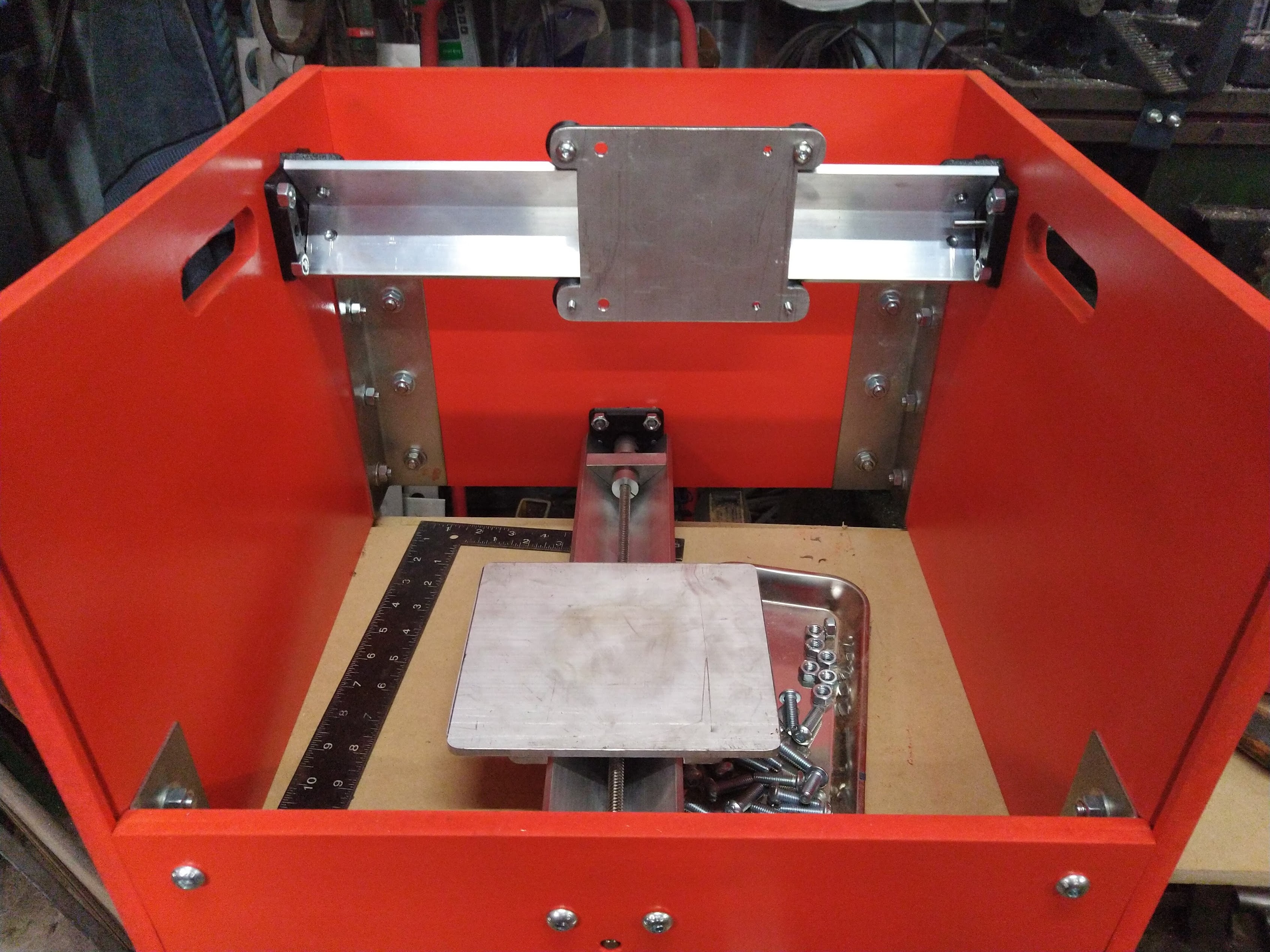
Another commonly cited issue with the Mill One’s design was that there was no bottom on the enclosure and so the enclosure was susceptible to going ‘out of square’. One solution is to add a bottom to the enclosure as has been done by others, but this for me takes away one other very useful feature - ease of clean up. My solution for this was to use much lager heavier duty corner brackets. These have made the enclosure very sturdy. I’m also considering adding a metal bottom frame to the machine but incorporate a removable tray to allow for easy clean up. I did consider using a sturdier material such as form ply, which has the added benefit of being waterproof which would allow coolant to be used but again this requires modifications to other aspects of the machine and so for this iteration at least, I decided to keep with the basic Mill One form factor.
Mechanically that’s about all I decided to do. Further improvements would take the design too far away from the original design intent, which was a cost effective desktop CNC made from accessible components.
There is one important thing worth mentioning here for anyone considering building their own Mill One from the Sienci plans. There is a mistake in the dimension of the XZ Gantry plates. The bearing mount centres are listed as 45.33 from the centre line. This is incorrect and will result in very loose carriages. The correct dimension is 44.88 as per the Y axis Gantry plate. I found this out after spending a few hours on the mill making super accurate gantry plates only to find they were loose and rattly when fitted up. Gutted :(
Electronics
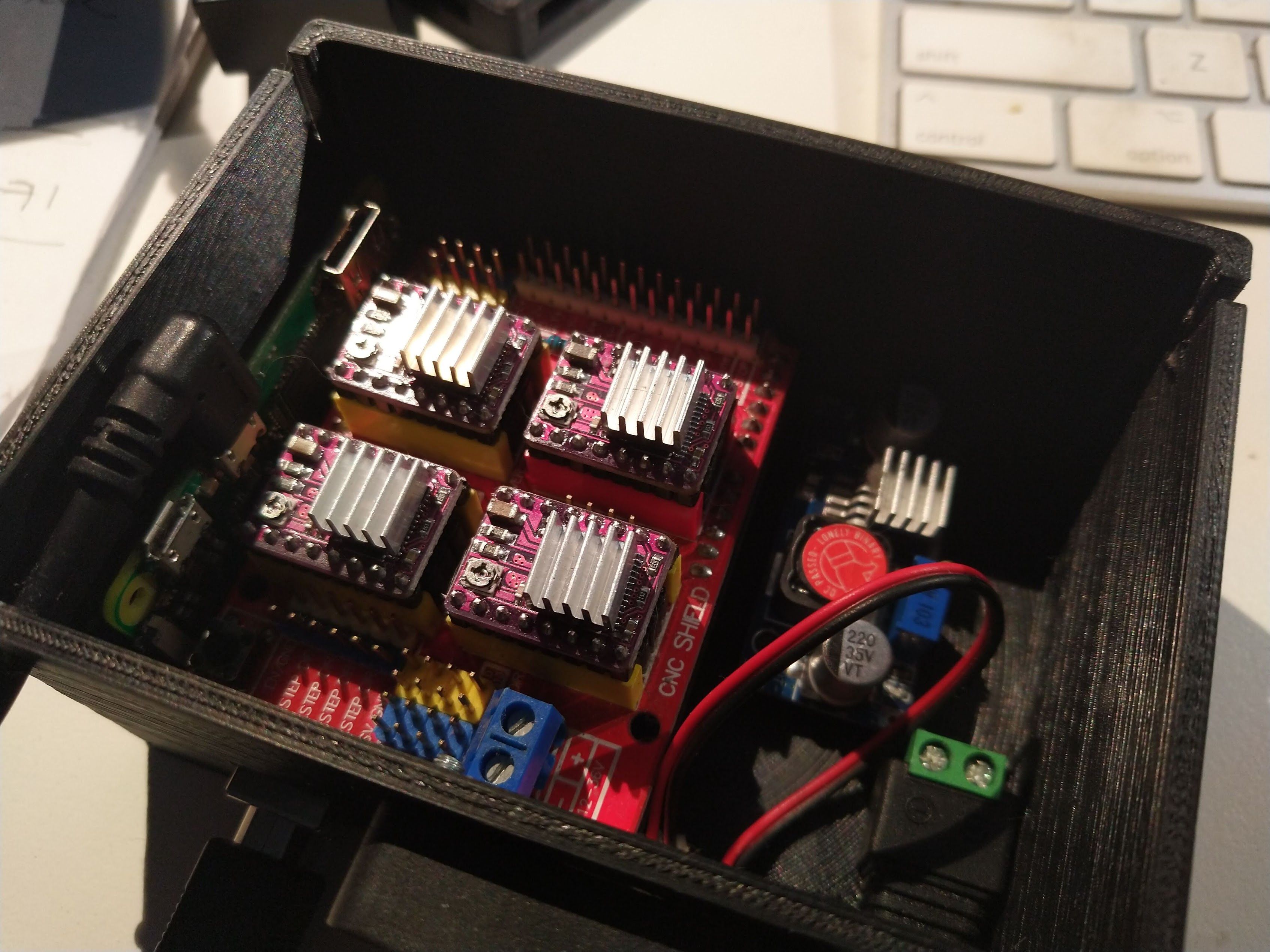
Next up I took a look at the electronics. The V3 Mill One already recommends larger stepper motors. I coupled this to some 8825 stepper drivers which are capable of handling much higher loads than the pololu 4988’s. I also took advantage of the 8825 stepper driver and Protoneer CNC shields ability to use a 36v supply which results in lower current for the same power output which helps reduce electrical load requirements on the system.
The other improvements that I made was to use a Zero Pi running CNCjs to act as a Gcode sender / server. The ZeroPi plugs into the Arduinos USB port and acts as a Gcode sender streaming data to it much like tethering it to your computer. The benefit of doing this is that the ZeroPi can be accessed wirelessly on your local WiFi network which means that it does not need to be tethered to a computer to work. To access it you simply go to your browser and access CNCNjs on the ZeroPi. This presents the CNCjs controls to you and allows you to control and operate the machine wirelessly. The machine then acts much more like a standalone CNC controller which is perfect if you run a lot of the same jobs as I do. There is no need to hook it up to a PC or search the network for job files, they are stored locally on the Zero Pi so all you need to do to run the job it load up the file, zero the stock and away you go.
Just on this point, I have a strong dislike for tethered machines, especially those that run Mach 3/4 or Linux CNC. I’ve used both of these in the past and both are fraught with problems. My opinion is that a machine shop is no place for a computer and neither Mach nor Linux CNC run well from a laptop. So using a standalone setup like the Sienci Mill One with an Arduino + CNC Shield + ZeroPi controller makes a lot more sense to me. There’s no cumbersome PC. The electronics can be mounted in a protective enclosure and the system is not reliant on the PC to run. Job setup can easily be done from a tablet.
I’m also taking a look into using an ESP32 based processor instead of the Arduino. These IOT boards have onboard bluetooth and wireless and so negate the need for the Raspberry Pi which will make the electronics part a little simpler and more compact. I have GRBL_ESP32 loaded up on an ESP32 powered UNO, I’ll create another post about this when I’ve got it up and running. The ESP32 port of GRBL is by Barton Dring. Barton developed it for his own ESP32 based CNC shields but it should work with the Uno layout board once the correct pin assignments are loaded up. The web interface is not quite as slick as the CNCjs setup, but if it can handle setting up and running the job then that’s good enough for me. The thing I’m playing with at the moment is a work-stream for bed levelling so that I can use the Mill One for PCB milling. Unlike 3D printer firmware like Marlin, GRBL does not have support for bed levelling. It can be supported in CNCjs as a plugin and this is what I’m getting set up at present. But I digress…
I would still like to add some control buttons to the machine for cycle start and cycle stop as well as incorporate a tool touch off probe of some kind. I’ll look at those in another post along with some performance tests. I also bought a small stand alone air pump to use for chip clearing and potentially mist lubrication / cooling. It’s actually an air pump from an airbrush gun. It puts out a fair bit of air volume. Hopefully with a suitable sized nozzle it will work.
I’m getting pretty excited about milling some aluminium projects. Hopefully the mods I have done have made it up to the job. I guess I will soon find out.