Improvements to a wood auger based plastics extruder
After some discussions on the Precious Plastics forums about adding compression to a wood screw auger based plastics extruder by various means, I had a bit of a eureka moment. Why modify the wood auger? Why not simply use this as a pattern to construct a brand new extruder screw of the correct characteristics?
The biggest drawback to using a wood auger for plastics transportation in an extruder is that it does not compress the plastic. This means when you use pellets as your plastics source, the air is not compressed out of the melt, which gives you bubbles in your extrusion. This is especially true when using irregular shaped granulated recycled plastics as your feed source. To overcome this, commercial extruder screws change dimensions along the length of the screw, compressing the plastic and forcing the air out. This pressure also helps to meter the extruder output.
The discussion over on PP was based around modifying the widely and easily available wood auger bits that people use to make DIY plastics extruders from, so that they had this same change is dimensions along the length of the screw. But this got me to thinking. The pitch of the auger bit is fairly good, it works to a degree as-is, it's just the compression factor that is the issue. So with the understanding that the pitch is acceptable, why not use it as a guide to make a better auger from scratch.
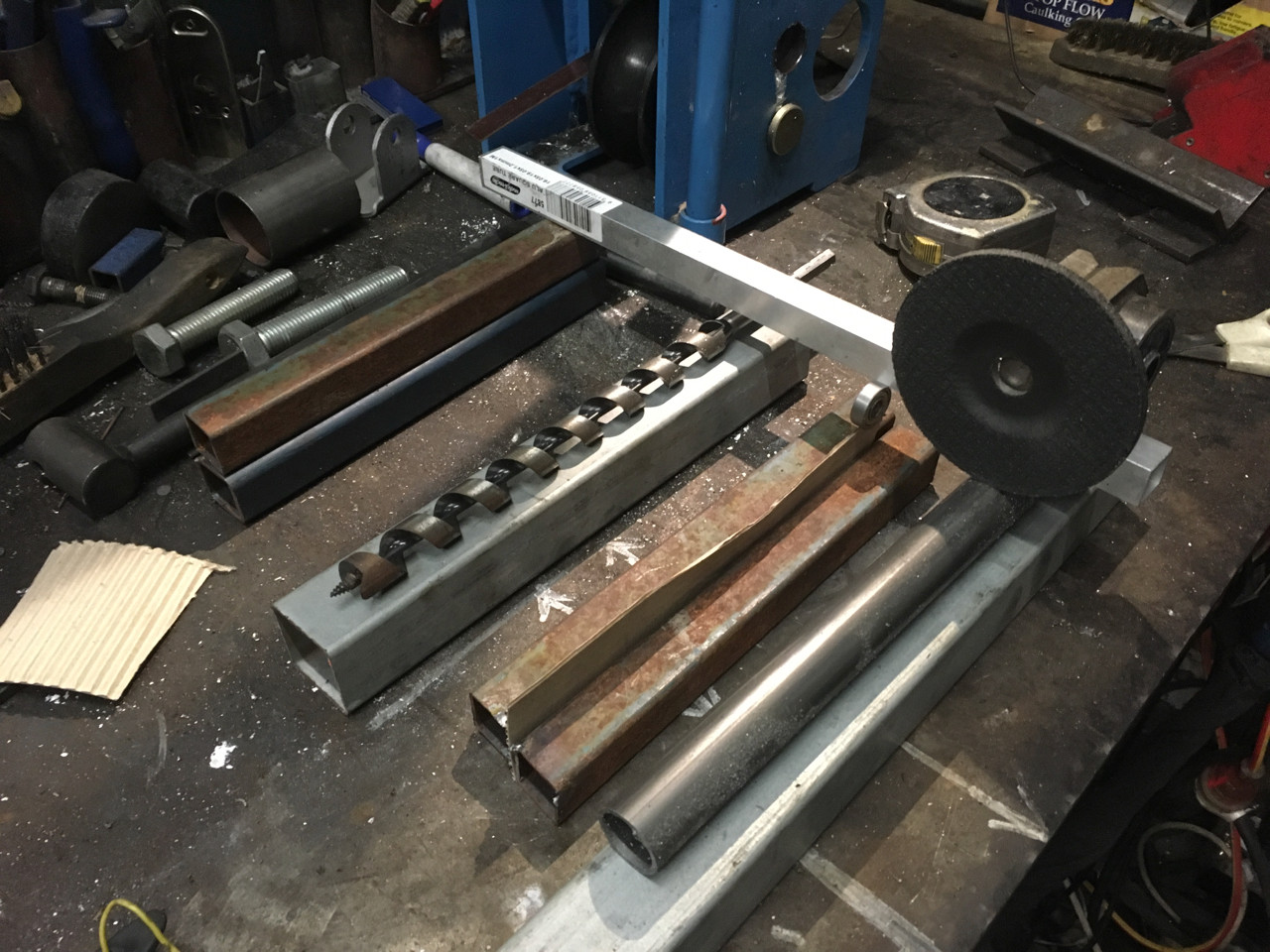
So based on this idea I have come up with a concept that can be used to fairly easily and quickly make a new screw from scratch out of steel bar, using an existing auger as a template / guide. You will need to use your imagination a little, but look at the photos and I will describe my idea...

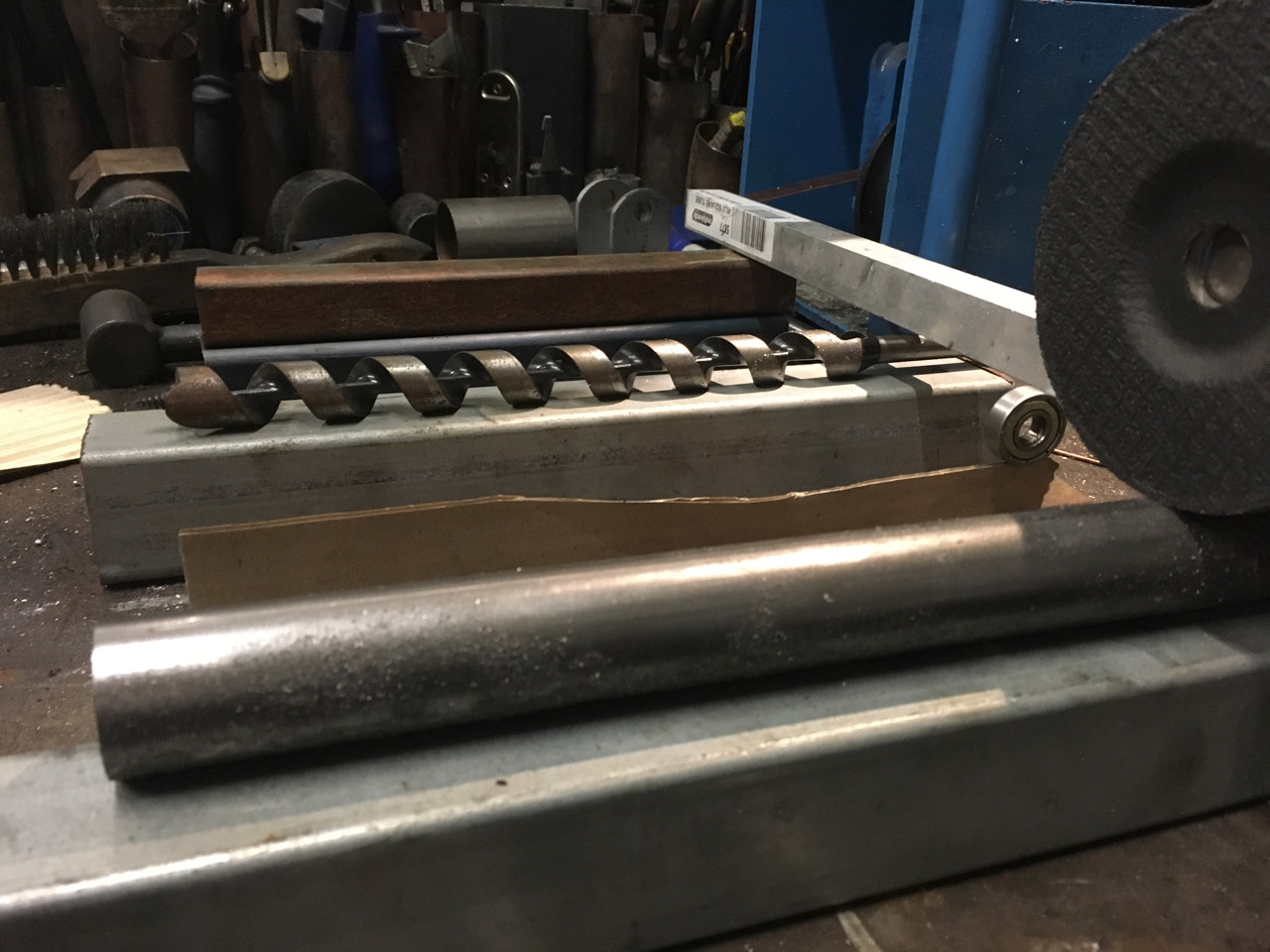
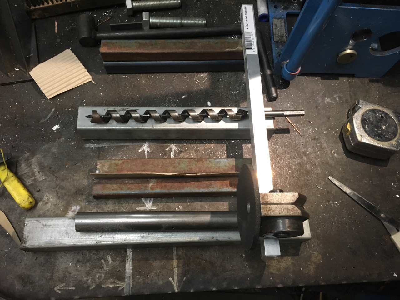
There is a moving table that uses the wood auger bit as it's lead screw. Onto this table an angle grinder is mounted. The grinder mount hinges at the end opposite to the grinding wheel (the handle end). This allows the grinding wheel to rise and fall.
The grinder assembly is supported on a bearing which runs along a cam (this is the cardboard piece in the photo but could be sheet steel). This cam is shaped to the desired profile of the root of the extruder screw. You should be able to see that my cardboard cam has a loading section, a compression section and a metering section. Changing root profile is as simple as swapping the cam.

The workpiece (represented by the steel pipe - nearest in the photo above) is mounted between centres. Ideally a live centre in a tail stock and a chuck. The chuck is driven from the wood auger on a 1:1 ratio using a timing belt.
As the chuck / wood auger is turned, the table holding the grinding wheel tracks the flute of the wood auger, which then grinds the same flute pattern on to the steel stock.

The grinder eventually grinds away the material until it reaches the cam, which prevents it from going any deeper, thus the root of the flute follows the cam profile.
By making the grinder have some adjustment along the axis of the workpiece, it also becomes trivial to grind the optimum 4:1 Root:Flight ratio from the auger. This can also be achieved by careful selection of grinding wheel width
Some thoughts:
- The 'nut' required to fit and follow the auger flute should not have any play. Some kind of bearing set up would be optimal. I did a quick eyeball with a 608 bearing and it should be easy enough to turn a steel 'tyre' that can be pressed onto the bearing that fits the auger flute. If you made three of these they could easily be mounted around the auger bit - a bit like a rudimentary ball screw
- I have found that different augers (of same size but from different manufacturers) have different pitches. Which pitch is best?
- The table motion can be inexpensively created using drawer runners, the grinder is available everywhere, same as the auger bit, the rest of it is just metal and time. This means that anyone could potentially make this device anywhere with little more than a welder and some hand tools.
- Some parts could be 3D printed to speed up manufacture, for example the 'bearing nut' for the ball screw and the grinder holder.
- By altering the pivot, grinder and cam follower relationship it should be possible to scale the output. Ie, you could use this machine to make a 50mm auger from a 20mm wood auger pattern. You can also do a similar thing by changing the cam profile.
- A more elegant method of construction would be using square aluminium extrusion or even makerslide or similar.
Summary
I think that a simple tooling fixture like this could potentially solve the issue of accessibility of manufacture for the essentially complex extruder screw. These screws generally require CNC manufacture, which is not always an option. By making a simple fixture such as this it would be possible to make an acceptable extruder screw that performs better than using an unmodified wood auger bit. It is also possible to make this from little more than scrap and without the need for a lathe or a mill, which to many is the major stumbling block.
If you use this method to make a screw, please let me know