DIY Extruder screw making machine Part 2 - Mounting the grinder
Last week I wrote about the extruder screw that I'm making and shared the initial build of a machine to make my own screw. In that post I created the basic table using an auger as a lead screw. This proved the concept of using an auger as the transport mechanism but when I started to build the second part, the mechanism that holds the grinder, I found that the auger was mounted too low in the frame and so the grinding wheel would not be able to reach the workpiece. So before I could get stuck into mounting the grinder I needed to move the 'lead screw' up on top of the frame.
Moving the lead screw also allowed me to change the design a little. After my initial tests you may recall that I decided that the nut design I had come up with was overly complex, in fact after doing some more experimenting I decided that the auger did not need to be held captive and enclosed within a nut at all. What I decided to do was simply run a bit of round bar over the top of the auger (I actually used a bolt as it was a little harder than round bar). The bolt is welded to the top of the slides and held against the top of the auger. The auger itself was positioned such that it engaged with the bolt with as little play as possible. Once I was happy with how everything was positioned I tacked it together and tested it out. The result is pretty good. It's not quite as smooth as the previous version with the bearings, but considering that the goal is to be able to make this with easily accessible materials and hand tools it's a win.

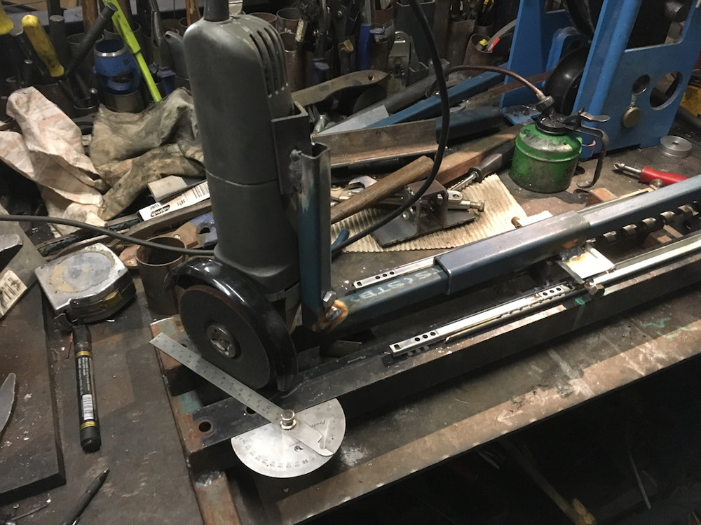
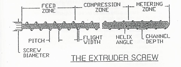
With the transport part of the machine fixed (again), I moved on to mounting the grinder. As you can see in the photo above the grinder mechanism is mounted to the moving 'table' with a simple hinge. This allows the grinder to move up and down and follow the profile of a cam. This cam defines the depth to which the grinder can cut, which effectively creates the variation to the depth of the flute. It is this variation in depth that creates the loading, compression and metering zones required in the screw profile as shown below.
But before we get too tied down in the cam design, we need to mount the grinder. The grinder has two threaded holes that are for attaching a handle to. I decided to use one of these to mount a small length of RHS to. The thread on my grinder was M8 so I simply drilled a hole through some 20x20 RHS and bolted it on to the grinder. I also added a bit of 20mm angle to the top so that the grinder could be strapped using a worm-drive clamp or heavy duty cable tie. I added a length of RHS to the bottom and braced it with a gusset cut from some scrap to give it strength and stop it from flexing. This entire assembly was then slid inside some larger RHS that was welded to a hinge on the slide. The sliding assembly can be locked in place by two M6 bolts. The adjustment allows the grinding wheel to be set to create channels wider than the width of the cutting wheel itself
A point to note was that the grinder was mounted at an angle of 60 degrees as this is the helix angle I measured on the auger.

I added an axle with some skateboard bearings at the ends that run along the cams. These bearings support the weight of the grinder. I will add some large washers to the inside of the bearings that will site in between the two cams so that the force of the grinding wheel does not cause the mechanism to deflect. With the bearings in place running along the cams the entire motion is very smooth and easy to turn.
All that is really left to do is to cut the cam profiles and finish off the mounting for the workpiece. Then it's time for testing.

As I'm fairly sure that my description and the dodgy photos make it hard to follow what's going on, here's some sketchy video of it doing it's thing...
Here's some more photos as well.