Robot Laser Scanner
Using an industrial robot as a laser scanning device
Photogrammetry
There’s lots of new ‘3D Scanners’ making it into the marketplace, many with simple point-and-film capturing carried out from household smart devices. The simplicity of being able to ‘paint’ the model into existence using nothing more than your mobile phone is impressive for sure, but can you actually use these models for anything useful? Well that depends. In reality the captures created by such systems are little more than augmented reality texturing, they are not really ‘3D scanners’ in the context of 3D parametric modelling. If you try and 3D print such models, you would end up with a featureless blob or at best an object that was missing much of the detail. The fact that these ‘scanners’ wrap the captured visual image around the model trick your brain into thinking that the fine detail actually exists on the model, but this is not the case.
So ‘Augmented Reality’ (AR) is really all that photogrammetry is good for as it is not dimensionally accurate. Having developed robotic 3D scanning some 20 years ago and being an avid follower of 3D scanning technology since this time I find that there’s too much of a crossover in terminology with these new school apps. Very little (literally none) of these photogrammetry kind of scanning apps are any good for reverse engineering, they cannot produce accurate 3D models or accurate point cloud data. On a side note I also find that the use of the expression AI (Artificial Intellegence) is also frivolously applied to a variety of technologies that have little or no connection to AI in its traditional sense. It sadly appears that the world as I once knew it is slowly dissolving.
Of course I’m not trying to take anything away from photogrammetry or AR, these are both amazing technologies, but to me it seems that there is confusion where people seem to believe that they can output CNC ready models. This is simply not the case. It’s not even close.
Expensive toys
Even commercial 3D scanners have limitations. A friend of mine had a part scanned and then asked for a 3D printed model so that he could verify the part dimensions. What he found was that there were discrepancies on the model, with the thinning of the part where it was scanned from opposing sides. This was on a ‘commercial’ grade hand held laser scanner costing over $10k. What this highlights is the issue that all hand held scanners have, fixing their location in space relative to the part. Without accurately knowing where the scanner is, without accurate locational data it cannot produce accurate model data. Many scanners utilise some form of implementation of a gyro, of the sort used in mobile phones, to get rotational cartesian components and then using the laser to measure the rectangular components. Many try to overcome this with using dots, or other points of reference, but they are all inaccurate solutions. This information is then combined within the capture app. but errors like the kind mentioned above show the inaccuracies of such systems.
Industrial scanners are an order of magnitude more expensive than these commercial grade systems and employ propreitary (and therefore expensive) spatial location sensor setups that are super accurate, and so they do actually return accurate data. But then this is why these kind of systems cost upwards of $50k. In comparison to these setups, photogrammetry is literally little more than a gimmick or toy.
So it is quite scary that $10k essentially just buys you little more than a toy, but then this is a view that I have long held, that these ‘cheap’ hand held scanners are not accurate enough to produce a model that you can then send straight to manufacture. In all of these systems there will be an amount of post processing to undertake on the resultant model before it is useful enough for manufacturing. The issue being that without tethering the sensor to its environment it simply does not know where it is and cannot give you accurate data.
Of course hand held systems are still a massive time saver when used for reverse engineering, especially with the manufacture of cast parts where a majority of the model does not need to be accurate and the accurate faces will end up being machined. In this kind of application, i.e. the manufacture of casting molds and plugs, these systems are a really good fit as none of the finished surfaces will come directly from the scanned data, they will be tidied up in post processing.
3D printed parts however rely on the entire model to be accurate as it is producing a finished part with finished surfaces directly from the model. This is where there is currently a big disconnect within this technology. Most people make the assumption that you can easily go from 3D scanned parts direct to 3D printing. In some cases this is true, for example on a turntable type system where the part is presented to a fixed laser scanner. With this type of system the laser imaging / scanning device is in a fixed relationship to the part so accurate data can be generated, however the size of the part is limited by the physical size of the scanner. Voids also become apparent where features of the part are essentially ‘in shadow’ and cannot be seen in a direct line of sight from the scanning sensor. (Note: I use the term ‘sensor’ loosely here.)
Enter # 2
Traditional methods for accurately measuring items usually employ some form of CMM (Coordinate Measuring Machine). On a large scale this usually employs some form of XYZ gantry whereas on a smaller scale something like a Faro arm is commonly used. Faro arms look much like an industrial robot and employ a similar kinematic model to generate cartesian (i.e. XYZ) point cloud data from the triangulation of axis angles. But whilst Faro arms are generally 5 axis, most industrial robots are 6 axis.
An industrial robot can also be used to do the same job, albeit not as accurately as a faro arm. The same principle apply: move the arm and present it to the part using a tool of a known dimension and then triangulate its position in space using the kinematic model from the robot arm. If we use a laser instead of a fixed tool, we can turn the robot into an automated faro arm, the laser means that the system is then ‘non-contact’ and does not need to touch the part. If we expand on the laser to return multiple points then we can quickly build up a model of point cloud data whilst the robot ‘scans’ the part.
I actually developed a similar system over 20 years ago for Fords and Mercedes - using a robot to scan car door aperture. This was for on the fly scanning + measurement + path offset. It was a proof of concept that we developed for automated door seal application, a process that was always traditionally carried out by hand. The necessity for measuring the car on the fly was because there are always deviation in location, both the physical location of the car when it enters the cell (they are usually on some kind of conveyor) and also the shape and location of the door aperture itself, which will vary due to tolerance stack up in how the panels are put together. This deviation means that it is impossible for a robot to tackle the task by standard path programming. This deviation is of no consequence to a human who simply adapts automatically.
First you scan the car to get baseline data…
Then you can control the robot in realtime… Note that in this example video this robot has no positional data, just a start and end point, it follows the cable using realtime scanning which it feeds back to the robot serially as offset data and then modifies the current position to offset the path on-the-fly
Combining the two systems the robot produces on-the-fly path corrections which are applied to path data which has been previously scanned by the laser. This minimises the actual on-the-fly correction and essentially means that the system ‘learns’ the object. Its machine learning and 3D scanning well ahead of the curve (about 20 years ago).
With this kind of setup the issue that all hand held devices have is overcome, however it still suffers from the same limitation that those small turntable scanners suffer from; that it cannot cater for really large parts: there is a maximum size that it can scan. Some of this limitation can be overcome by adding additional axis to the robot. A turntable is an obvious first choice, a linear axis to extend its reach and make it a travelling arm could be employed. But where do you stop? How far do you take this idea? at some point the cost of such a system outweighs the benefits it produces, which brings us back to those hand held scanners. Maybe $50k is the price-point for such a system. After all a new robot cell capable of loading up an object and scanning it will probably run into about $250k by the time you buy a robot a 7th axis turnable and develop the laser vision system and software to do the job.
At the end of the video it flashes an image of the processing application, you can just make out the car door aperture profile and the x,y offset that is fed back to the robot. This is the reflected light pattern from the stripe laser that is picked up by a camera. It’s a similar process use in all laser scanners. The software takes the point data and identifies a specific feature which it then returns the offset data from, but it can also use all of the measured data to return point cloud data. Imagine a constant stripe / stream of data. You would end up with point cloud density that had too many points for the average computer to handle. Back then we had special servers that processed this point cloud data. Mind you, that was 20 year-ago technology. Things have come a long way since then.
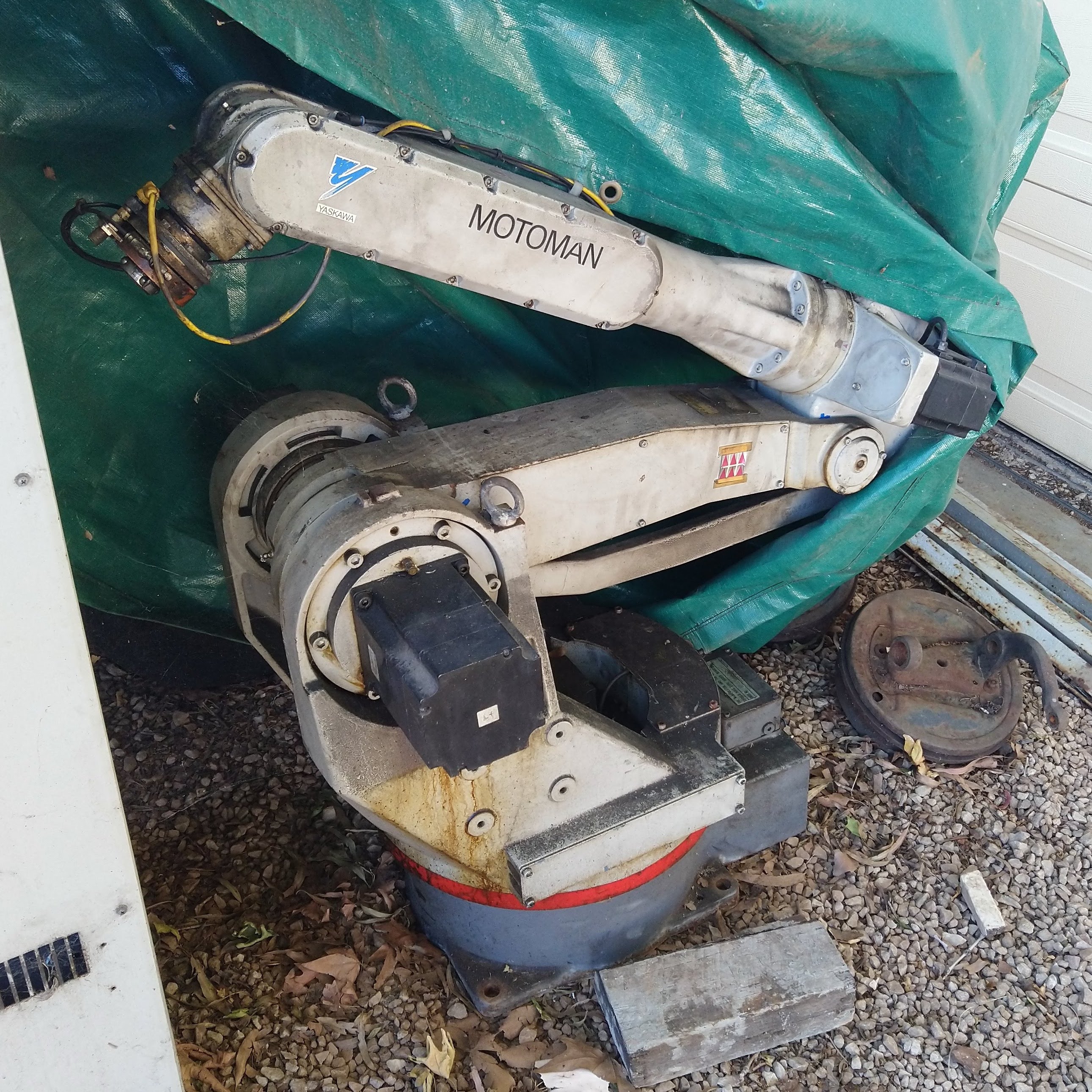
My Motoman MRC SK16
So I ‘inherited’ a Robot from a manufacturing facility where I was manufacturing manager. Truth be told, when it closed down and after auctioning everything off, all of the lots that were turned in aat auction were simply scrapped, so this unit was literally about to go into the bin. After a conversation with my manager and the hasty hire of a trailer I rescued it from getting put into the scrap metal bin along with all of the other scrap. It’s a very old MRC controller and SK16 arm. It was used in a spot welding cell and despite being the oldest unit in our factory, it was ironically the most reliable. I like to think that’s because all of the newer XRC based controllers ran from a version of Windows CE, whereas the older systems like this used a proprietary embedded controller. We can still see this divide today with the differences between systems like the Raspberry Pi and Arduino, where automated repetitive tasks being more suited to the Arduino’s architecture.
So the robot has been sitting in my driveway for the past few years without a job to do, but now after discussing laser scanners with my friend (the same friend that had the part scanned) I’ve decided that a 3D laser scanner is a good project to get it recommissioned for, plus very soon I will get a huge chunk of my garage back when some storage is feee’d up. I also figure there’s a bunch of other uses I can put the robot to once it is up and running.
There is however unfortunately a lot of limitations with the MRC controllers, they are now thirty years old and it ran from a very simplified instruction set. There’s no serial data ports or data manipulation of any kind in these older style controllers so the ability to directly access positional data is not present. But there is the opportunity to access program data using the floppy port. Yes, you heard correctly, the MRC used a floppy device connected to a serial port for data backup. (See I told it was old). Serial data communications and string manipulation is pretty straightforwards so I should be able to extract the cartesian data from the program backup
The cost of laser micrometers (the key part) is also prohibitively expensive, so I’ve also decided that it is simpler to build my own laser scanning head using the same principles we used 20 years ago in the video. Essentially it’s a very similar technology now employed with those open source turntable style scanners, a stripe laser and a video camera. The smarts are in the image processing software. Back then we used Visual Basic 6 and a ROBcad server, but now I feel confident to use a Pi Zero and write the code in Python. It’s entirely possible to make the system self contained within the sensing head. The Pi is definitely good enough to process the data and it only needs a few peripheral connections to be able to hook up to the robot, the aforementioned serial connection and also a simple handshake to control the arm. Once the resultant STL file has been created it can be accessed via the Pi’s ethernet connection. Workflow will simply be loading up a part pressing go and then waiting for the STL file to be automagically generated.
Also, I will try and locate a cheap 7th axis for the MRC but this may also be too expensive, if indeed one can be found. So it is also likely that I will use the Pi to drive a DIY turntable. This is not overly difficult to achieve using a stepper or servo and to a degree possibly simplifies things given the limited command set of the MRC.