ESPduino + Protoneer CNC Shield
If you’ve been following my recent posts on building a new improved Sienci MillOne you may recall that I wanted to experiment with using an ESP32 board rather than the Arduino UNO / Rasberry Pi setup that I already had set up.Well after some experimentation I now have the MillOne running under ESP32 control.
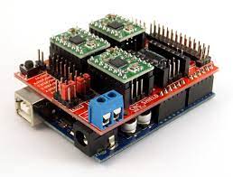
Setting up the Protoneer CNC Shield was pretty straight forwards, in fact the only modification that needs to be undertaken is to remove the end stop resistor R1 as this cases the ESP32 into an endless loop of resetting which prevents it from booting up. Simply removing the resistor fixes this issue.
The ESP32 boards are 3.3v, which may initially seem an issue when using a shield designed for the 5v UNO. However there is no onboard circuitry on the shield to cause a problem. Both the 4988 and 8825 stepper drivers accept 3.3v signals and the ESP32 board has its own power input. It’s a similar story with I/O pins which basically connect direct to the ESP32.
What this all means is that you can simply plug the ESP32 into the CNC Shield without needing to worry about anything.
One thing that I could not find in the current GRBL_ESP32 release was a machine file for the ESPduino / CNCshield. There is one in older commits but at some point it seems that there was a code refactoring and it simply disappears. So I decided to create a new file instead. I based the file on several different versions that I found scattered around the interwebs and added some additional relevant settings in there for completeness. The resulting file is below
#pragma once
// clang-format off

/*
		espduino_protoneer.h
		Part of Grbl_ESP32

	   Protoneer CNC Shield with ESPduino board


		2021    - DeeEmm

		Grbl_ESP32 is free software: you can redistribute it and/or modify
		it under the terms of the GNU General Public License as published by
		the Free Software Foundation, either version 3 of the License, or
		(at your option) any later version.

		Grbl is distributed in the hope that it will be useful,
		but WITHOUT ANY WARRANTY; without even the implied warranty of
		MERCHANTABILITY or FITNESS FOR A PARTICULAR PURPOSE.  See the
		GNU General Public License for more details.

		You should have received a copy of the GNU General Public License
		along with Grbl_ESP32.  If not, see <http://www.gnu.org/licenses/>.
*/

#define MACHINE_NAME "ESPDUINO_PROTONEER"

#define X_STEP_PIN      		GPIO_NUM_26  // Uno D2
#define X_DIRECTION_PIN  		GPIO_NUM_16  // Uno D5
#define X_RMT_CHANNEL			0

#define Y_STEP_PIN      		GPIO_NUM_25  // Uno D3
#define Y_DIRECTION_PIN   	    GPIO_NUM_27  // Uno D6
#define Y_RMT_CHANNEL			1

#define Z_STEP_PIN      		GPIO_NUM_17	// Uno D4
#define Z_DIRECTION_PIN   	    GPIO_NUM_14	// Uno D7
#define Z_RMT_CHANNEL			2

// OK to comment out to use pin for other features
// #define STEPPERS_DISABLE_PIN GPIO_NUM_12	// Uno D8

#define SPINDLE_PWM_PIN    GPIO_NUM_19    // Uno D12 (Spindle Enable)
#define SPINDLE_PWM_CHANNEL 0
// PWM Generator is based on 80,000,000 Hz counter
// Therefor the freq determines the resolution
// 80,000,000 / freq = max resolution
// For 5000 that is 80,000,000 / 5000 = 16000
// round down to nearest bit count for SPINDLE_PWM_MAX_VALUE = 13bits (8192)
#define SPINDLE_PWM_BASE_FREQ 5000 // Hz
#define SPINDLE_PWM_BIT_PRECISION 8   // be sure to match this with SPINDLE_PWM_MAX_VALUE
#define SPINDLE_PWM_OFF_VALUE     0
#define SPINDLE_PWM_MAX_VALUE     255 // (2^SPINDLE_PWM_BIT_PRECISION)

#ifndef SPINDLE_PWM_MIN_VALUE
		#define SPINDLE_PWM_MIN_VALUE   1   // Must be greater than zero.
#endif

#define SPINDLE_PWM_RANGE         (SPINDLE_PWM_MAX_VALUE-SPINDLE_PWM_MIN_VALUE)

#define SPINDLE_DIR_PIN		GPIO_NUM_18	// Uno D13

#define COOLANT_FLOOD_PIN 	GPIO_NUM_34  // Uno A3
#define COOLANT_MIST_PIN   	GPIO_NUM_36// Uno A4

#define X_LIMIT_PIN      		GPIO_NUM_13  // Uno D9
#define Y_LIMIT_PIN      		GPIO_NUM_5   // Uno D10
#define Z_LIMIT_PIN     		GPIO_NUM_23  // Uno D11
#define LIMIT_MASK      		B111

#define PROBE_PIN       		GPIO_NUM_39  // Uno A5

// comment out #define IGNORE_CONTROL_PINS in config.h to use control pins
// #define CONTROL_RESET_PIN         GPIO_NUM_2  // Uno A0
// #define CONTROL_FEED_HOLD_PIN     GPIO_NUM_4  // Uno A1
// #define CONTROL_CYCLE_START_PIN   GPIO_NUM_35  // Uno A2 ... ESP32 needs external pullup


// defaults
#define DEFAULT_STEP_PULSE_MICROSECONDS 10
#define DEFAULT_STEPPER_IDLE_LOCK_TIME 250 // stay on

#define DEFAULT_STEPPING_INVERT_MASK 0 // uint8_t
#define DEFAULT_DIRECTION_INVERT_MASK 0 // uint8_t
#define DEFAULT_INVERT_ST_ENABLE 0 // boolean
#define DEFAULT_INVERT_LIMIT_PINS 0 // boolean
#define DEFAULT_INVERT_PROBE_PIN 0 // boolean

#define DEFAULT_STATUS_REPORT_MASK 1

#define DEFAULT_JUNCTION_DEVIATION 0.01 // mm
#define DEFAULT_ARC_TOLERANCE 0.002 // mm
#define DEFAULT_REPORT_INCHES 0 // false

#define DEFAULT_SOFT_LIMIT_ENABLE 0 // false
#define DEFAULT_HARD_LIMIT_ENABLE 0  // false

#define DEFAULT_HOMING_ENABLE 0
#define DEFAULT_HOMING_DIR_MASK 0 // move positive dir Z, negative X,Y
#define DEFAULT_HOMING_FEED_RATE 25.0 // mm/min
#define DEFAULT_HOMING_SEEK_RATE 500.0 // mm/min
#define DEFAULT_HOMING_DEBOUNCE_DELAY 250 // msec (0-65k)
#define DEFAULT_HOMING_PULLOFF 1.0 // mm

#define DEFAULT_LASER_MODE 0 // false

#define DEFAULT_X_STEPS_PER_MM 200.0
#define DEFAULT_Y_STEPS_PER_MM 200.0
#define DEFAULT_Z_STEPS_PER_MM 200.0 // This is percent in servo mode...used for calibration

#define DEFAULT_X_MAX_RATE 1500.0 // mm/min
#define DEFAULT_Y_MAX_RATE 1500.0 // mm/min
#define DEFAULT_Z_MAX_RATE 600.0 // mm/min

#define DEFAULT_X_ACCELERATION 30.0 // mm/sec^2. 50 mm/sec^2 = 180000 mm/min^2
#define DEFAULT_Y_ACCELERATION 30.0 // mm/sec^2
#define DEFAULT_Z_ACCELERATION 15.0 // mm/sec^2

#define DEFAULT_X_MAX_TRAVEL 235.0 // mm NOTE: Must be a positive value.
#define DEFAULT_Y_MAX_TRAVEL 185.0 // mm NOTE: Must be a positive value.
#define DEFAULT_Z_MAX_TRAVEL 100.0 // This is percent in servo mode...used for calibration
These settings are for the MillOne but if you have a different machine you can easily adapt these to suit.
The I/O is mapped to mimic the standard Protoneer CNC Shield layout. This means that they are as per the silk screen descriptions on the shield itself. You may choose to alter these to suit your configuration. This is especially true with some inputs as external pull-up resistors are required and so swapping them over to other pins can make your wiring easier.
I’ve raised a pull request to get this integrated into the project but will have to see if it is accepted. There could be a valid reason why the old files were removed. At any rate I thought I’d include it here for my own future reference as well.
If you have any mods or comment relating to the file, please feel free to hit me up on Discord (Link at top of page)
/DM