Carvey CNC

Carvey
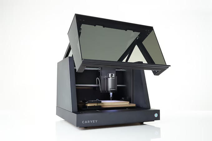
I’ve long been a follower of the desktop CNC scene and was pretty impressed when the Inventibles Carvey was released. It was a very professional looking machine greatly different to the typical CNC routers made from bolt together extrusions. It’s most appealing features were the enclosed workspace and simple workflow, similar to the Sienci MillOne in that it placed importance on the requirement for a proper enclosure to be used as a true desktop machine. Unfortunately however, the price tag was not so appealing.
Fast forward to last month and a Carvey appears on my local auction-bouse listings. An opportunity that might result in a more reasonable price, an opportunity too good to pass up. I figured that even if the machine needed fixing, it was the perfect basis for a true desktop CNC format that I could use in my office, something that I have tried to build with the MillOne. And so, after a bit of bidding it was mine.
Taking Check
The machine had come from the local university, which can be both a good and bad thing. Good in that they generally don’t see much use, but bad in that they are often misused and abused. The machine had definitely not seen that much use. In fact it still had all of the original accessories along with the test material supplied with the machine. It was also fairly clean and did not have a massive buildup of cutting dust, so looks like a win on that count. But the win was short lived as when I tested it I discovered that there was drift on the X axis. Misuse? Possibly. But also entirely likely just down to poor design or manufacturing.
I suspected that the issue might be just due to stepper driver tuning, as this is a typical issue found on stepper based CNCs. But when I started to dig a but deeper I found that the stepper drivers are integrated into the main board and there was no way to set the current limits or change the driver.
Support
I spoke to support about the issue who said that replacement main boards were available at US$1000, which was more than I paid for the machine. They were helpful enough in providing some documentation but did not offer any kind of repair service. So I decided to order a replacement driver chip and swap it out myself. Unfortunately changing the chip did not fix the issue, which means that I now have to resort to Plan B
Plan B
Plan B is to junk the controller in favour of something else. It really should not be too hard to convert it to use a regular generic 3 axis Arduino based CNC controller board, there’s heaps of different types available. The Arduino Uno based CNC V3 shields are cheap and readily available and a good candidate for a simple 3 axis machine. These may be old but they really do the job well. These are exactly what I used on my MillOne.
As an upgrade these boards can also be used with the UNO style ESP32 boards instead of the Arduino UNOs which not only gives you 32 bit architecture it also gives you WiFi connectivity and web browser control when loaded with something like GRBL_ESP32 or the newer version Fluid_NC. These are both GRBL based CNC control firmwares and a step up from regular Arduino-GRBL. They can also be used with DRV8825 stepper drivers, which can exceed the 2A provided by the original Trinamic Stepper drivers, and will also work at 48V. I have used this exact setup in the past on my Mill One. The result is a much more capable machine.
All existing limit switches can be reused, same with the hold/continue button which gets you a moving machine, however there are a few additional things to address…
It needs a DC-DC converter to give the required 5v for the controller and LEDs. It also needs a DC-DC PWM spindle controller to drive the spindle, but these are also cheap and plentiful. The other option here is to upgrade the spindle from 300w to a 500w or even 800w unit that comes with a PWM controlled PSU (commonly referred to as mach3 control). Lastly I need to remap / connect the pins on the shield to the machine, which is not a massively hard job to do and is made much easier by the documentation supplied by the Carvey Tech support.
The smart clamp can also be reused. It should be possible to write a macro to search the smart clamp and apply a work coordinate Z offset. I use a similar setup on my Mill One which probes for X,Y and Z.
Both GRBL_ESP32 and FluidNC can work tethered to a Gcode sender like Easel / ChilliPeppr / cncjs / etc, or can be used completely stand alone by loading the GCode file into local memory via the web browser. Running the machine as stand alone eliminates issues with comms / computers / wifi / timeouts / screensavers / etc. This is always my preference, especially on big jobs.
It’s definitely possible to replace the controller with an alternative and not only does it not need to break the bank, you can actually get a better system at the end of it.
I have most parts but need to order a 24v PSU buck and DC Speed controller.
Info from schematic
Other basic info from the schematic:
There’s two power supply stages - one from 48v down to 24v and then another from 24v down to 5v.
Interestingly my PSU unit is only 3.34A which is not actually big enough to cater for two steppers and the spindle all simultaneously at full load (which is a foreseeable scenario). I think this is definitely one area I will address.
It appears that the LEDs are 0-5v PWM controlled and look to be fed from the 24v supply. I’m guessing that there may be some local circuitry for the door and spindle LED clusters. Will definitely need to verify this with some testing.
The cover switch looks to be a simple volt-free switch with the electronics included on the main board to inhibit the spindle and steppers and provide feedback to the ECU.
The button LED appears to be 5v and fed direct from the ECU via PWM (note: signal conditioning is present)
Spindle control is via MosFET similar to most basic DC motor control circuits.
Door control
The magnetic door interlock is actually a bit more complex than just being connected to the feed hold input. Electronically it is connected to the spindle controller and each of the axis. Opening the door electronically drops the spindle relay out and holds the X,Y and Z step signal lines low via transistors, which physically kills all movement. This is exactly as it should be - a hardwired safety circuit, not a software based safety circuit. Whilst it is not quite up to required SIL or CAT safety levels for this type of machine, it is heaps better than simply initiating a stop in software which is what 99.9% of hobby CNC’s do.
Inventible’s have been very thoughtful in how they have implemented this and I assume that it was driven by the requirements for using this type of machine in schools and collages. Of course, more complicated control systems means more things to go wrong, but that’s the trade off.
In addition to the hardwired stop, a signal is also sent to the cover_switch input of the uC most likely to halt the program operation as well. (haven’t looked at the gCarvin code)
I’m not sure if I am going to replicate the door control electronics for my build. It’s not necessary for my environment and use case, and does over complicate the upgrade, however I do want my kids to be able to use this so I will definitely implement a software hold as a minimum. Cutting the 48v via a relay is the simplest option, but this does not bring the machine to a controlled stop, it also makes recovery difficult as the machine will be in an unknown position (due to inertia). All of these issues are addressed with the original design. Will have to ponder this a little more before deciding.
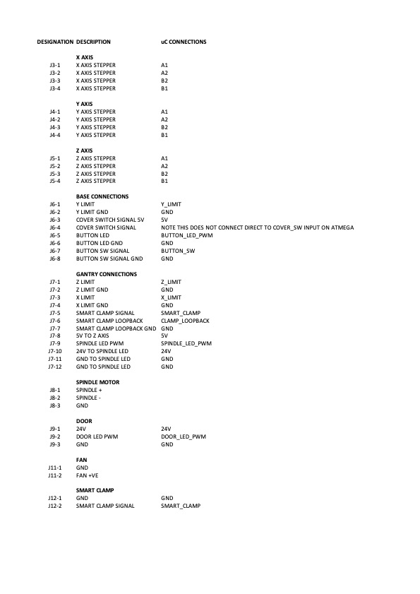
Pin Designations
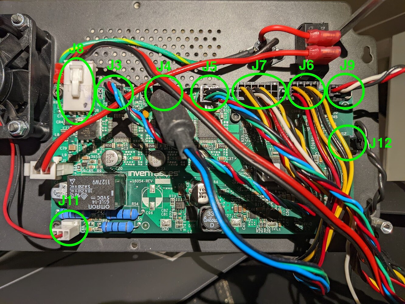
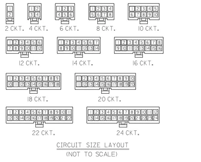
Going through the schematic and picking out the board connections has allowed me to create a wiring schema. Each of the molex plugs is labelled J followed by a number, i.e. J1, J2 etc.
The wiring is grouped together by function and area. Spindle / gantry / base / etc.
I’ve overmarked a photo of my board with the plug designations which you can cross reference with the pin outs below.


J12 connects to the smart clamp. The schematics also show this signal available on J7-5. This is not a mistake it appears to be connected to both sockets.
I’ve previously posted pin-outs for the ESP32duino and protoneer CNC shield…
https://deeemm.com/cnc/2021/07/15/ESPduino-protoneer-CNC-Shield.html